 |
UAH EE-100 Concepts in Digital Signals and Systems Digital Temperature Gauge using the OOPic Student Project 11/15/1999 By Jeff Richeson University of Alabama in Hunstville Electrical and Computer Engineering Department |
|
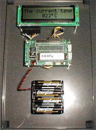
My project is based on a device called OOPic. OOPic is an acronym for "Object Oriented Programmable integrated circuit". This is the new and unique kind of processes controller. The February 2000 issue of Popular Electronic (now Poptronics) will have an article on the OOPic as the next generation of process controller. This project will measure the temperature with a high level of accuracy and display it on a LCD panel.
This device is a single chip multitasking computer designed to be programmed with a "Visual Basic 5.0" style of compiler on any standard IBM compatible computer. It features a removable nonvolatile EEprom for storage of the runtime program and it is "Hot Swappable", the board has a second socket for even more EEprom for data logging or a co-processor. It also has an on board 5-volt regulator which allows for a wide range of power supply voltages to be used to power the unit. There is a 40-pin connector on one side that has all I/O, Raw voltage, 5 volts regulated, ground, and the local I2C bus available. This connector fits to a standard 40-pin IDE disk drive type of cable for expansion products that will be available soon. The nice thing about this device is that while it is multitasking, it is also networkable. This allows the OOPic to be networked with up to 127 other OOPics, with each one having it’s own node. Another feature is that each OOPic and address up to 10 bits of address space for co-processors or memory on the Local I2C bus, this makes for a very powerful multi-processor, multi-tasking environment. (See figure #1)
 Figure #1 |
The OOPic has a number of predefined hardware objects, software objects and something totally new, virtual circuits. All of the objects or circuits are programmable from the compiler.
Hardware objects are items that are actual hardware inside of the chip. These items are like analog to digital converters, timers, counters, pulse width modulators, serial ports, servo ports, Digital I/O ports and more.
Software objects are item like Math objects, debounce objects, converter objects, randomizer objects and more. Software or processing objects are defined by the compiler and are downloaded into the EEprom, as they are needed during the Make process.
Virtual circuits is a bit hard to explain in words but, in a nutshell, these are gates and connections between object that are described in the compiler. This is how you would look at an input port and "AND" this with an analog converter and send the value to another object for further processing. Basically this is how objects are connected together.
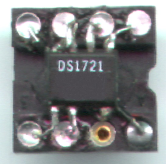
My project uses the OOPic to setup a smart temperature co-processor (see figure #2) located on the local I2C bus to do constant 16-bit temperature readings (this processor is in a SO-8 package which needed to be converted to a standard 8 pin package see figure #3) then the OOPic converts this 16-bit number to 8-bits. After the number is converted to 8-bits, it then send the value to the LCD screen. The LCD screen is a standard off the shelf device with an 8-bit port, although I have configured it to work in a 4-bit nibble mode for convenience. Because the power supply comes up too quickly on the LCD screen for the internal reset routine to initialize, I have to initialize the display though a sequence of code (see program listing #1). I then send text "The current temp". I then go to the instruction register of the LCD screen and index the memory pointer to the location corresponding to the right of where the temperature will display, and send the decimal equivilant of the temperature with the STR$() command, followed by a "%C" This is happening simultaneously while the object "oI2C" is running and acquiring data from the temperature co-processor.
|
|
|
|
The materials and procedures needed for this project were:
The first thing that I did was to decide what I wanted in a project that might serve me in the future for other home projects. The OOPic came to mind because of its extreme flexibility and its reusable. This was very appealing to me since I enjoy building electro-mechanical devices.
The next thing I had to decide was, what task would I make the OOPic perform that would be useful. I decided that the best thing would be a temperature controller and thermometer. This was a tough job to do because the OOPic is such a versatile device.
I now had the task of deciding the project specifications so I would not go way beyond the scope of this course. This was tough because I wanted to show it off a little but, common sense prevailed and you will see what I finished up with. I did not even come close to exploiting every function of the temperature co-processor or the OOPic in this project, but it would have been very easy to do so.
This particular project makes a useful device for measuring temperature in a remote or local location very easy. This is something that I can build upon for other interest that I have regarding energy conservation and solar utilization.
One of the things I like about this project is that, I had the unique position of being a Beta Tester for the OOPic before it was released to the market. Being in this position was fun because a lot of my likes and dislikes were incorporated or corrected in the final product before public release. I also had access to the String Basic compiler Beta.
The documentation is on-line at http://www.OOPic.com and is being updated daily. This approach to an online manual is nice because the information is always fresh and correct.
| Program listing #1 - Updated 01/27/200 for OOPic String Basic. |
'This program used the String Basic Version of the OOPic compiler,
'which at the time of this writing is in Beta.

  Dim D As New oDio4          'Initializes a new object called D as a nibble I/O
  Dim E As New oDio1          'Initializes a new object called E as a single bit I/O
  Dim RS As New oDio1         'Initializes a new object called RS as a single bit I/O
  Dim thermo as New oI2C      'Initializes a new object called temp as an I2C port
  Dim thermo8bit as New oByte 'Initializes a new object called temp8bit as a 8 bit byte
  Dim LCD as New oDataStrobe  'Initializes a new object called LCD as a Data Strobe

  Sub main()
    'Start of main program
    Call IOSetup                    'Calls sub program Setup
    Call ThermoSetup                'Calls sub program TempSetup
    Call LCDSetup                   'Calls sub program Configure
    LCD.String = "The current temp" 'Write the text to the LCD
    Do                              'Start of do loop
      thermo8bit = thermo/255       'Convert 16 bit temp into 8 bit value
      Call SetLoc                   'Calls sub program TempLoc
      LCD.String = STR$(thermo8bit) + "%C" 'Write the temp to the LCD
    Loop                            'End marker for do loop
  End Sub                           'End of main program

  Sub SetLoc()
  'Routine to locate the cursor for the Temp
    RS = 0                   'Sets Register Select to Control Register
    D = 12:Call StrobeE      'Sets the address of the degree number Hi nibble
    D = 06:Call StrobeE      'Sets the address of the degree number Lo nibble
    RS = 1                   'Sets Register Select to Data Register
  End Sub

  Sub IOSetup()
  'This routine sets the IO lines that are connected to the LCD display
  'and configures the Virtual Circuit to do the Data Strobe.
    D.Iogroup = 3    'I/O group used for nibble out to LCD
    D.Nibble = 1     'Which nibble to use Upper or Lower
    D.Direction = 0  'Direction of data flow in or out
    E.IOLine = 27    'Which I/O line to use for Display enable and strobe
    E.Direction = 0  'Direction of data flow in or out
    E = 0            'Output value = high -- display is enabled
    RS.IOLine = 26   'Which I/O line to use for Register Select
    RS.Direction = 0 'Direction of data flow in or out
    RS = 0           'Output value = low -- Instruction Register
    LCD.Output.Link(D) 'Connect the datastrobe's data to the LCD's data I/O line
    LCD.Strobe.Link(E) 'Connect the datastrobe's datastrobe to the LCD's E I/O line
    LCD.Mode = cv4Bit  'Select 4-bit mode
    LCD.Operate = cvTrue ' Turn the Datastrobe object on.
  End Sub

  Sub ThermoSetup()
  'Routine to setup I2C communications and Temp Co-Processor
  'Temperature Co-Processor is started in 12 bit mode, the defalt state
    thermo.Node = 73           'Identifies node address for Temperature Processor
    thermo.Width = cv8Bit      'I2C object is set to 8 bit data mode
    thermo.Mode = cv7Bit       'I2C object is set to 7 bit address mode
    thermo.Value = &h51        'command to start temperature measurement
    thermo.Width = cv16Bit     'I2C object is set to 16 bit data mode
    thermo.Mode = cv10Bit      'I2C object is set to 10 bit address mode
    thermo.Location = &hAA     'Location of temperature registor in Temperature Processor
    thermo.NoInc = cvTrue      'I2C object does not auto increment the location
  End Sub

  Sub LCDSetup()
  'This routine performs LCD reset and initialization and
  'configures LCD display to operate in 4 bit nibble mode
    D = 3:Call StrobeE
    D = 3:Call StrobeE:      ' data is 8 bits here
    D = 3:Call StrobeE:      ' data is 8 bits here
    D = 2:Call StrobeE:      ' data is 8 bits here
    D = 2:Call StrobeE:      ' sets data length to 4 bits
    D = 8:Call StrobeE:      ' sets # of display lines & font
    D = 0:Call StrobeE:      ' sets display off
    D = 14:Call StrobeE:     ' sets display off
    D = 0:Call StrobeE:      ' sets display on
    D = 6:Call StrobeE:      ' sets display on
    D = 0:Call StrobeE:      ' entry mode set
    D = 1:Call StrobeE:      ' entry mode set
    D = 0:Call StrobeE:      ' entry mode set
    D = 12:Call StrobeE:     ' entry mode set
  End Sub

  Sub StrobeE()
  ' This routine causes the I/O line labeled E to toggle
  ' one time to strobe data into LCD's internal memory
    E = 1
    E = 0
  End Sub
|
Questions or Comments richeson@hiwaay.net
Other Interesting Links
|